Table of Contents
Trackball of Doom

I bought a 25 years old trackball on Allegro (Polish EBay equivalent). Although the electronics were… peculiar, it was really easy to connect to the encoders and buttons. What's more - they work :) Since I'm chiefly a rather high-level programmer, this is somewhat new to me, so please forgive some little blunders:]
Some brief research indicates that this was probably used to operate a radar or a similar device - it was manufactured by Thomson-CSF, who deal primarily in radars.
The rewired trackball is now at our hackerspace.
Level 1 - reverse engineering the electronics


The original circuit was based on TI 54xx series parts - they're a military grade version of the familiar 74xx series (http://en.wikipedia.org/wiki/7400_series). We have some counters, NAND gates, shift registers and differential line drivers there - if you're interested in details, there's an annotated version here. Apart from the button backlight (which does work, and which is absolutely useless except maybe in total darkness) everything you can see in the picture above can be replaced with a tiny Arduino program.
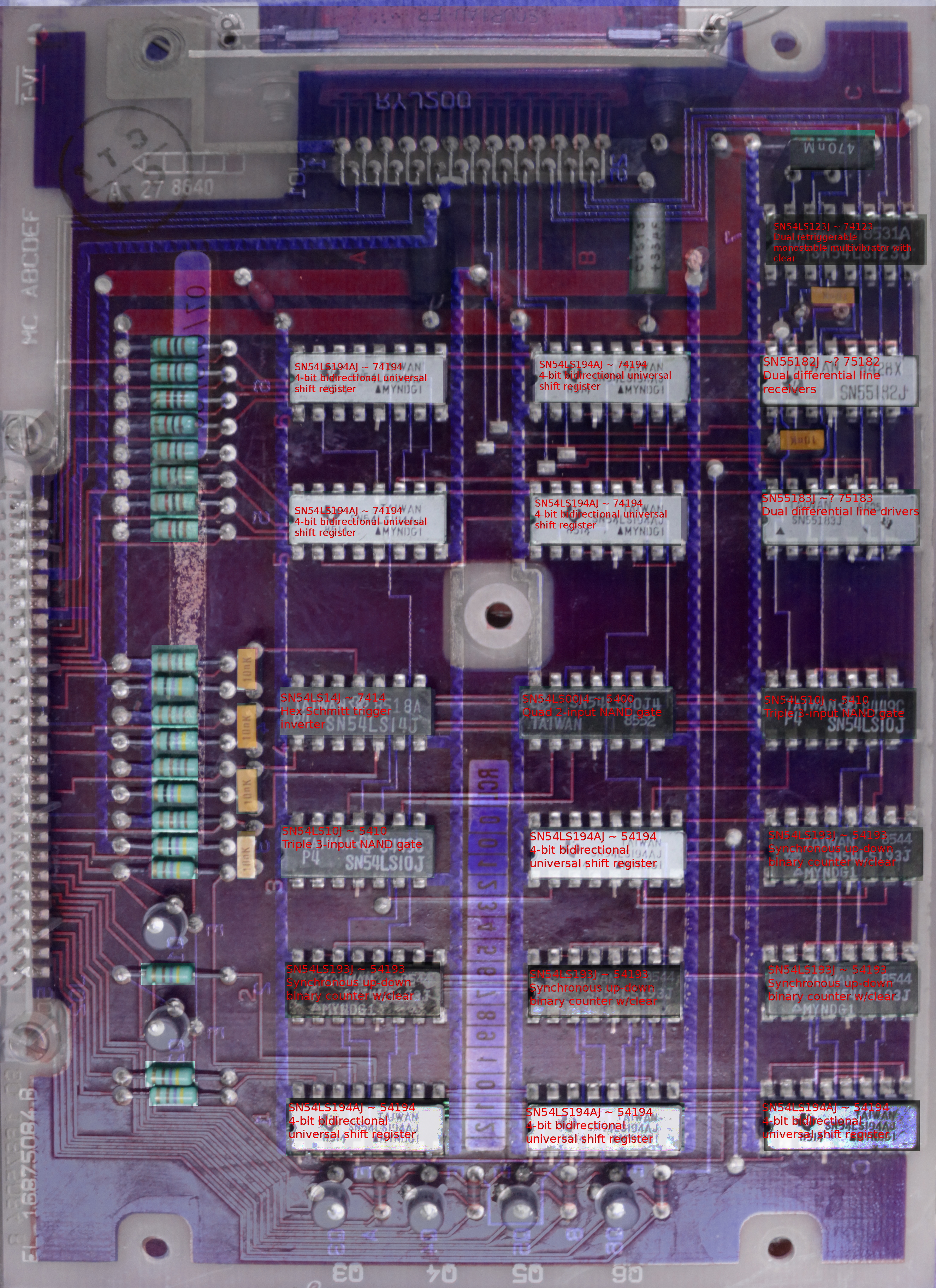
Note: the picture to the left is just a composite of two photos I took of the board's both sides, perspective adjusted and color-coded. I wish we had an X-ray, but not just yet :>
Level 2 - Emerythduino


The board I used is our homebrew arduino clone, you can take a look at it here: Devboard ATmega32U4.
The cable leading from the trackball to the board has both photo interrupter and button signal lines directly exposed. They were originally connected via pullup resistors. Fortunately the ATmega32U4 chip used on our board has internall pullups which are sufficient here. The Kabel-Salad you are looking at is a result of the way ground and VCC are routed on the cable - each encoder and button has their own. Since Arduino comes with a Mouse library, turning the signals into a USB mouse was quite trivial.
Below is the arduino sketch currently being used:
const int enc1 = 0;
const int enc2 = 1;
const int enc3 = 2;
const int enc4 = 3;

const int toggle = 8,
  lmb = 9, mmb = 10, rmb = 11;

int v1,v2,v3,v4, p1,p2,p3,p4,
  counter, dx, dy;
void setup() {
  pinMode(enc1, INPUT);
  digitalWrite(enc1, HIGH);
  pinMode(enc2, INPUT);
  digitalWrite(enc2, HIGH);
  pinMode(enc3, INPUT);
  digitalWrite(enc3, HIGH);
  pinMode(enc4, INPUT);
  digitalWrite(enc4, HIGH);
  for(int i = 8; i < 12; ++i) {
    pinMode(i, INPUT);
    digitalWrite(i, HIGH);
  }
  Mouse.begin();
}

void loop() {
  v1 = digitalRead(enc1);
  v2 = digitalRead(enc2);
  v3 = digitalRead(enc3);
  v4 = digitalRead(enc4);

  if((v4 ^ p4) || (v2 ^ p2)) {
    dy += ((v2 ^ v4) ? -1 : 1) * ((v4 ^ p4) ? 1 : -1);
  }

  if((v1 ^ p1) || (v3 ^ p3)) {
    dx += ((v1   ^ v3) ? -1 : 1) * ((v1 ^ p1) ? 1 : -1);
  }
  if(counter % 100 == 0) {
    if(digitalRead(lmb)) {
      Mouse.press(MOUSE_LEFT);
    } else if(Mouse.isPressed(MOUSE_LEFT)) {
      Mouse.release(MOUSE_LEFT);
    }
    if(digitalRead(mmb)) {
      Mouse.press(MOUSE_MIDDLE);
    } else if(Mouse.isPressed(MOUSE_MIDDLE)) {
      Mouse.release(MOUSE_MIDDLE);
    }
    if(digitalRead(rmb)) {
      Mouse.press(MOUSE_RIGHT);
    } else if(Mouse.isPressed(MOUSE_RIGHT)) {
      Mouse.release(MOUSE_RIGHT);
    }
    if(digitalRead(toggle)) {
      Mouse.move(0, 0, -dyc);
    } else
      Mouse.move(dx, dy, 0);
    dx = 0, dy = 0;
  }

  p1 = v1;
  p2 = v2;
  p3 = v3;
  p4 = v4;
  counter += 1;
}
That's all, folks
Below you'll find a little demo of the device. You can also try it out the next time you visit our Hackerspace.
— Tomek Dubrownik 2013/06/09 12:16