Table of Contents
Hello, World! From scratch
By the end of this tutorial, your MYiR board will write out a „Hello, Warsaw Hackerspace!” message on its' serial port. The code will be running without Linux on the first ARM core. The MYiR will boot from the SD card, using a file called BOOT.bin. This file can be copied to any SD card and the code will run just fine.
Preparations
Clone q3k's zturn-stuff repo, and install the ZTurn Board Definition as per the README.
In Vivado
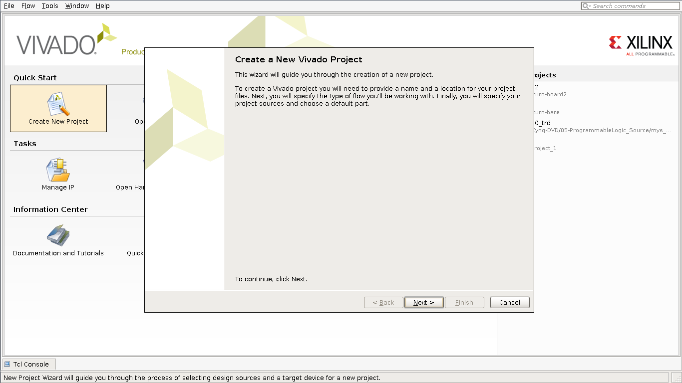
Create a new project
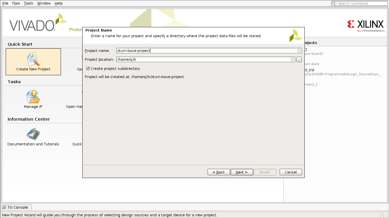
I chose zturn-base-project as the project name, which will be kept through this tutorial.
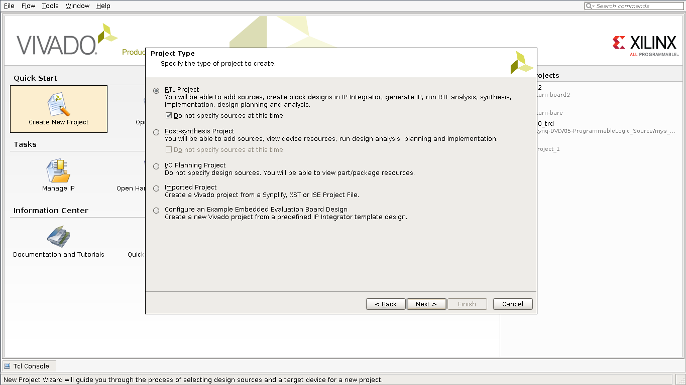
Select RTL project. We will not add any sources for now, so you can tick the relevant checkbox, or skip the next few steps.
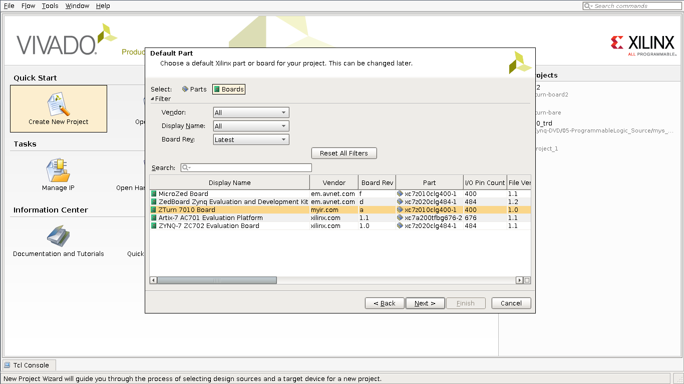
Choose the ZTurn Board. If you can't see this option, then you probably didn't install the board definition from the repo correctly.
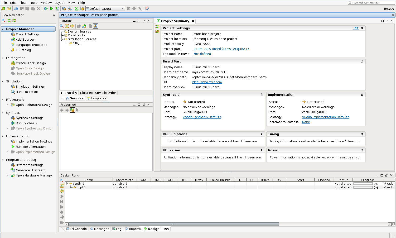
Admire the project view
This is how the Vivado project should look like when created. Nothing to see here for now. If you have a small display, you can hide the left panel as it's not super useful. Some other panels can be resized so you can focus on the Project Manager.
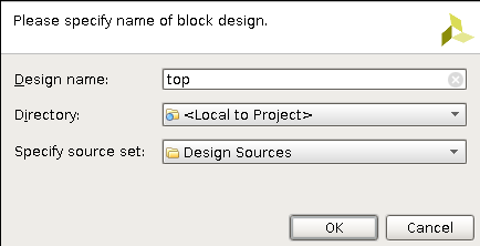
Create a new block design
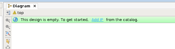
Here we will add the Processing System (==Zynq) wrapping block design to our project. First, create a block top-level view.

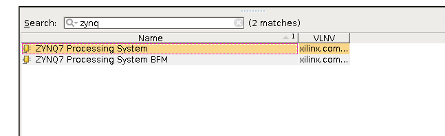
Then add the Zynq PS to it.
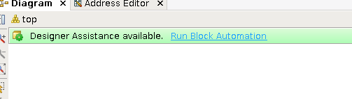
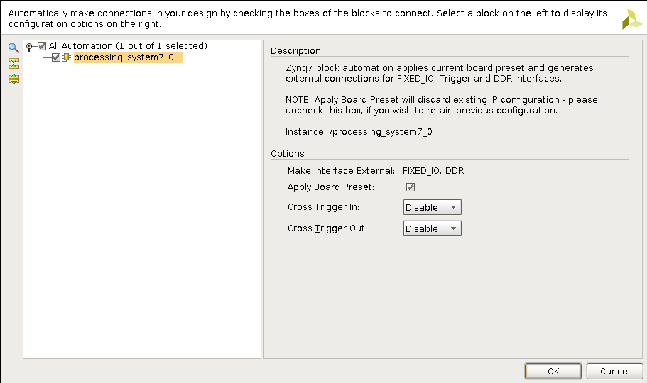
Run Automation
We can now run the TCL automation from q3k's board definition - this will set up clocks, peripherals and everything needed to get the ARM core and most peripherals somehow running, according to how the ZTurn board has been designed.
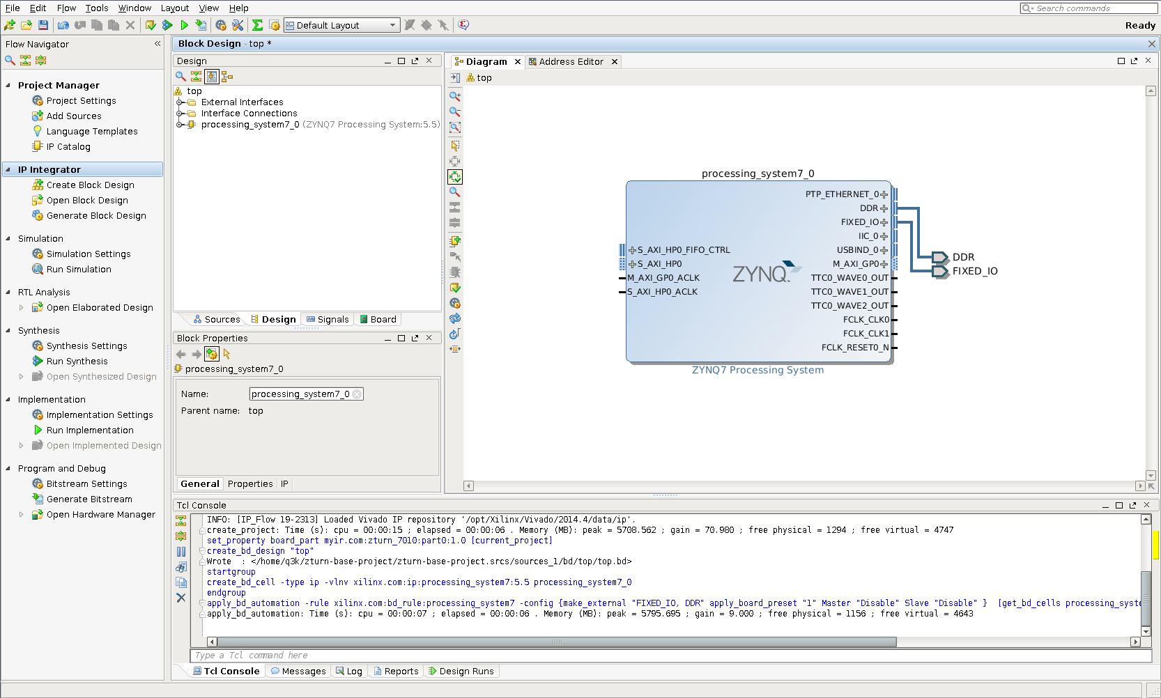
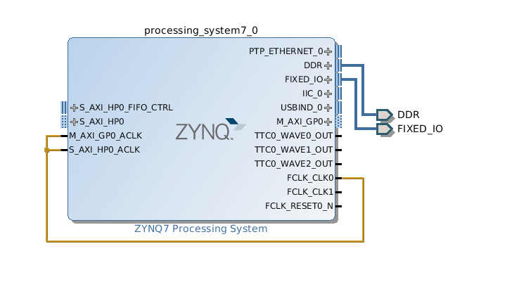
And here's how the block diagram will look after automation:
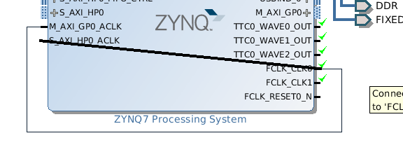
Connect clocks
This board requires the AXI busses to be clocked from fabric clocks. Don't worry about this too much right now, just connect the clocks as shown below.
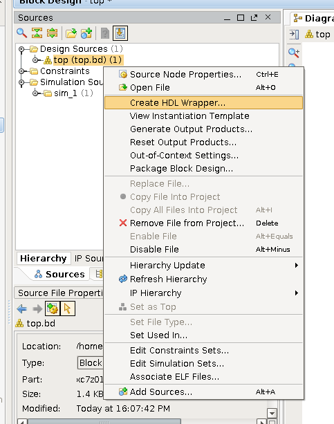
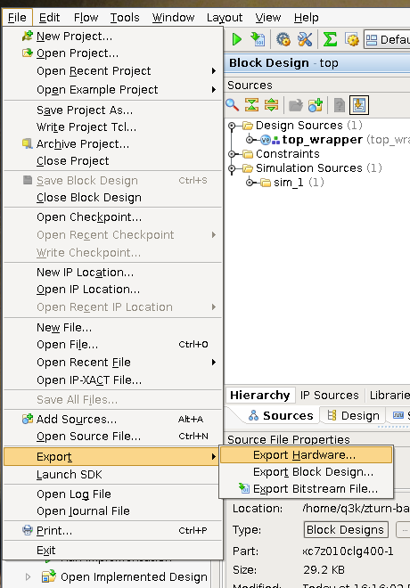
Export to SDK
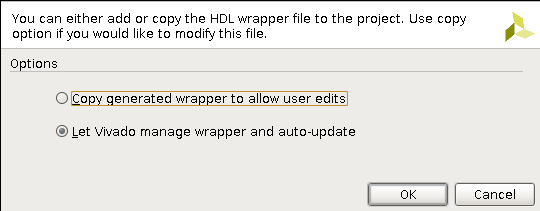
We will now generate a HDL wrapper from the top design. This means that clocks we drew and the block setup will be transformed into a Verilog file.
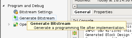
We can now generate the bitstream (which will take a while)… Watch the console window and top-right corner for progress.
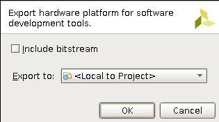
And export the Hardware Definition File. This is the main file used by the Xilinx SDK to understand the board setup and generate an appropriate bootloader that will set these options on boot.
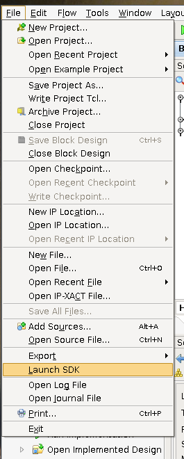
Then, launch the SDK…
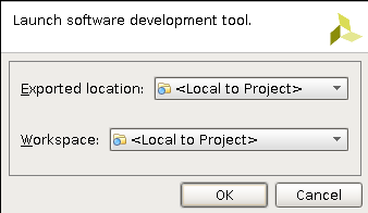
In Xilinx SDK
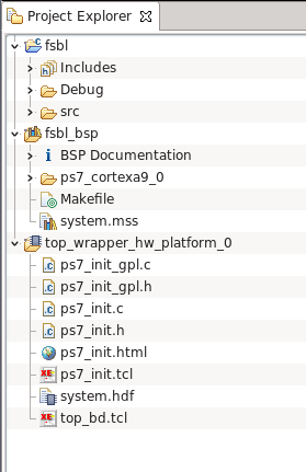
Rejoice! It's Eclipse.
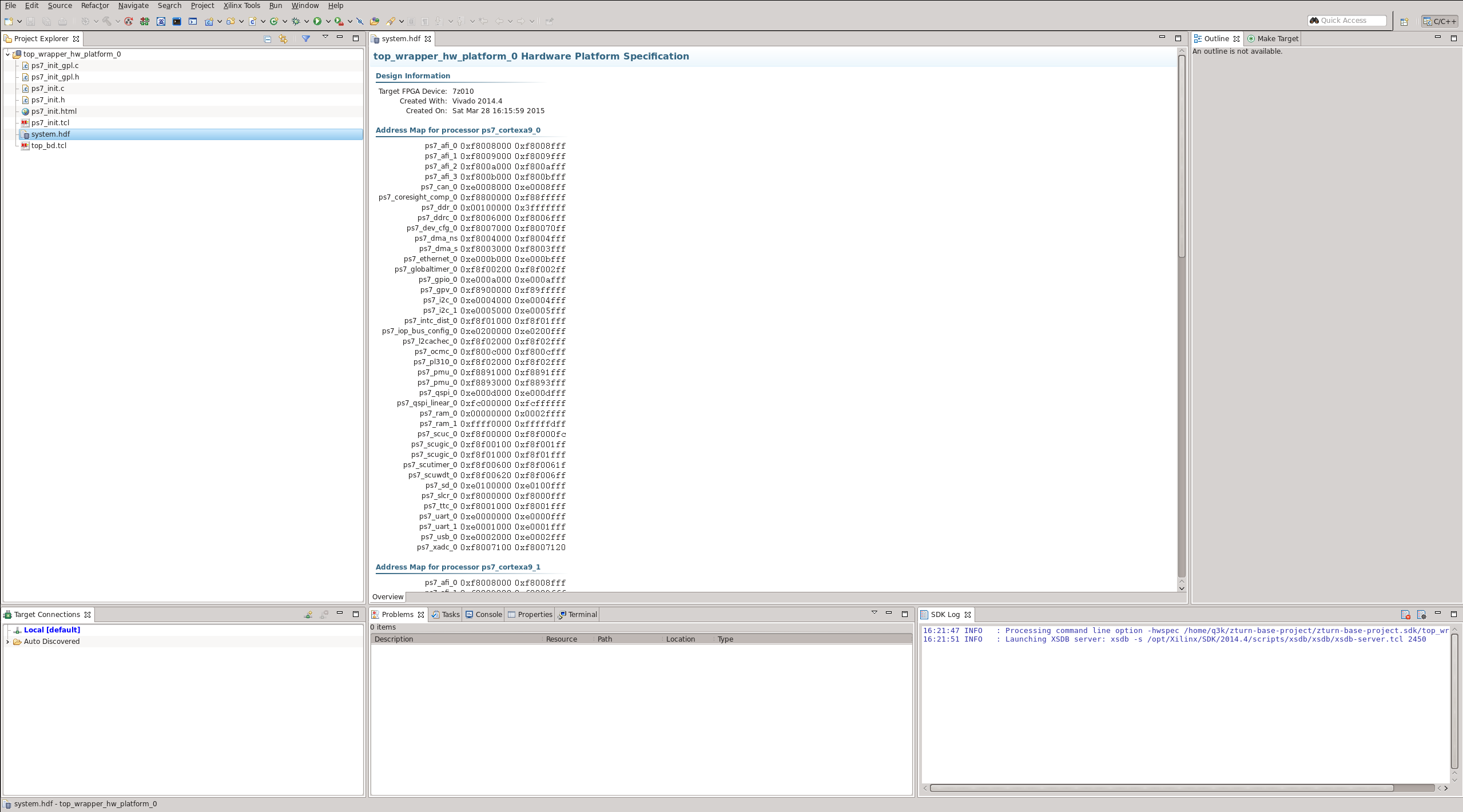
The top_wrapper_hw_platform_0 project is the HDF we exported from Vivado.
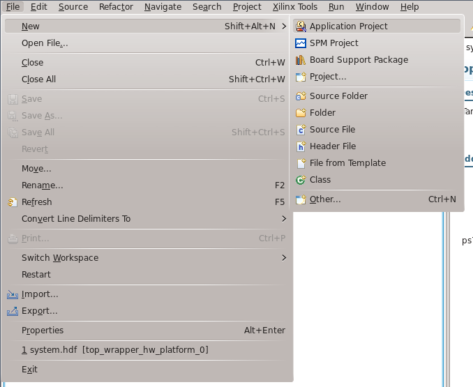
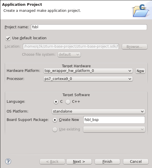
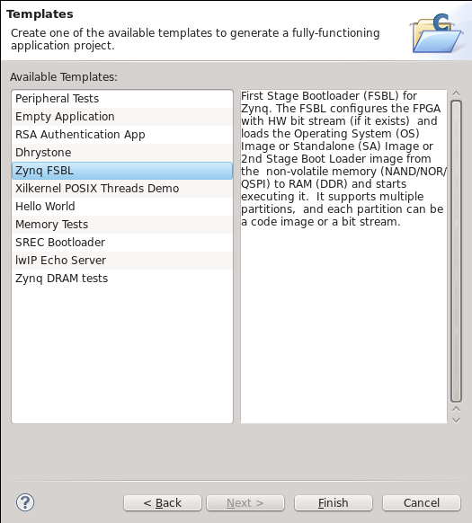
Create the FSBL
The FSBL, or First Stage Bootloader, is the first code loaded and ran from the SD. It will set up the FPGA and peripherals as set in the Vivado block (via the HDF file). It will then load a bitstream and second-stage ELF from the SD card, and load and run them as well. These three parts will be combined as a single BOOT.bin file.
The FSBL also requires a BSP (board support package) to be created. This BSP contains standard I/O functionality and other basic functions (like SD card access, threads, exceptions…). Both the FSBL and our hello world app will use this BSP.
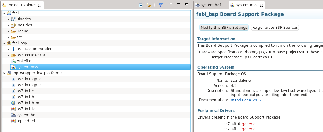
Here's how our workspace looks after creating the FSBL and BSP:
Let's modify the BSP to change the STDIO UART from UART0 to UART1. This is the UART that is available over USB on the board. Select system.mss in the BSP project, and click 'Modify BSP Settings'.
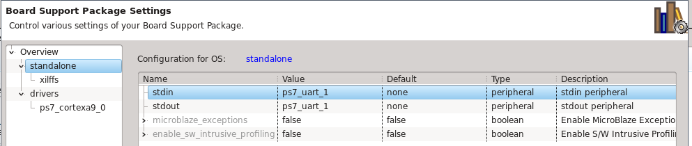
In the standalone options, select UART1 for both output and input.
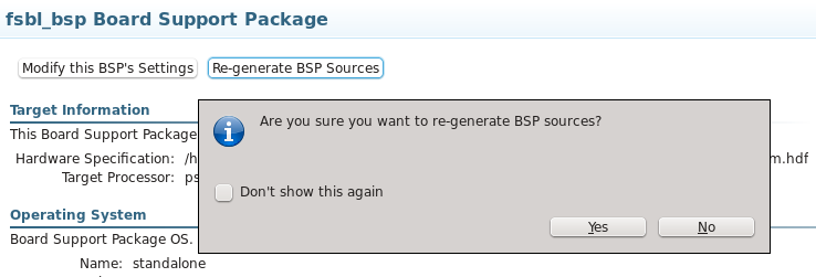
Afterwards, regenerate BSP sources.
Create the Hello, World! application
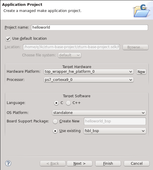
Now we're ready to write a bare metal Hello World application. Again, create a new application. This time, however, select a Hello World template instead of an FSBL template. Reuse the same BSP as for the FSBL.

Do some hardcore low-level programming.

Create the BOOT.bin image
Let's create the final image. It will contain:
- The FSBL ELF (in project/project.sdk/fsbl/Debug/fsbl.elf
- The FPGA bitstream (in project/project.runs/impl_1/top_wrapper.bit)
- The Application ELF (in project/project.sdk/helloworld/Debug/helloworls.elf)
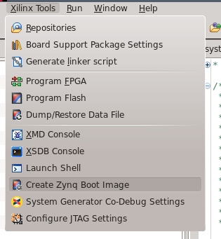
Run the image tool…
Create a new BIF file. Next time, you can just reload this BIF file.
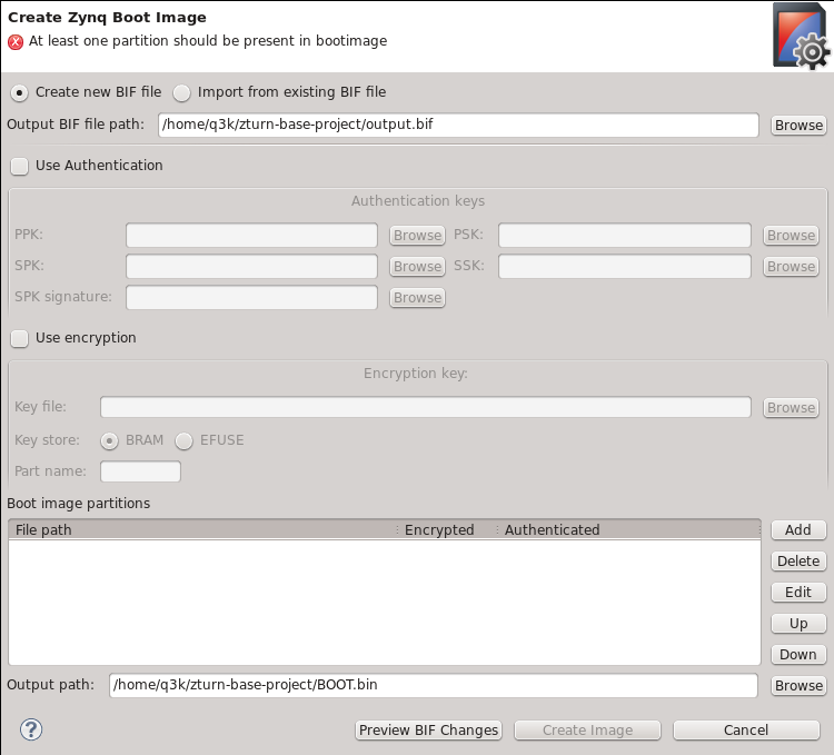
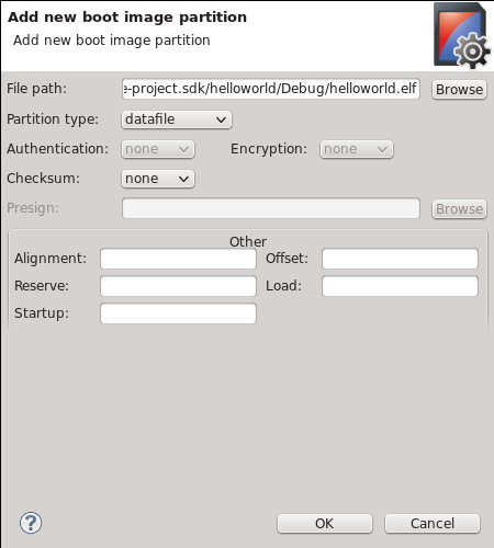
Add all partitions by clicking the 'add' button in the main image creator view, and fill out as follows:


Click 'Create Image' on the main image creator view. This will create the BOOT.bin file, which you can then copy onto a FAT32-formatted SD card. Boot the ZTurn board from it, and you should see your Hello, World! appear on the serial console on 115200 baud.