serial-display-shield:hardware
Table of Contents
Hardware
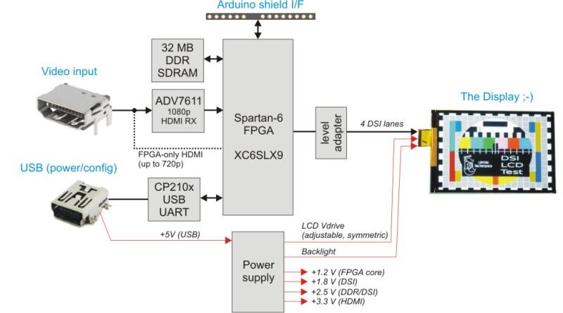
The block diagram is shown below:
The main blocks are:
- Xilinx Spartan-6 FPGA - XC6SLX9-3TQG144. Highlights: amateur-friendly TQFP144 package and built-in serdeses rated up to 1080 Mbits/s (fast enough to drive a 4-lane 1080p screen). The FPGA does pretty much everything in this project.
- DSI Level adapter: a bunch of resistors interfacing the FPGA's 1.8 V SSTL/LVCMOS I/O to DSI levels. More info on the FPGA core page.
- DSI connector: a standard 2x15pin 2mm pitch female connector with all DSI signals, power supplies and some GPIO pins for interfacing with the display. Since connector pinouts differ between displays the idea here is to use a tiny adapter board hosting the particular LCD's connector and its wiring.
- DDR SDRAM, providing memory for the framebuffer, since most smartphone DSI displays don't have one.
- HDMI input: slow version, using FPGA's ISERDES blocks (up to 720p) or a fast one (1080p @ 60 Hz), based on Analog Devices' ADV7611 chip. The external HDMI decoder shares some pins with the SDRAM chip and the host interface, so the full HD version can only work as a HDMI to DSI adapter.
- Host interface: 12 pins wired to Arduino shield's IOH/IOL headers. Exact functions are not defined yet, I'm thinking about a 4-wire SPI interface and an 8-bit parallel bus.
- USB UART a CP2102 chip providing USB UART and JTAG functionality for the FPGA.
- Main power supply: integrated PMIC (TI/National LM26480). Voltages are: +3.3 V (HDMI input, USB, host I/F), +2.5 V (SDRAM and FPGA Vccaux), +1.8 V (DSI), +1.2 V (FPGA core).
- LCD bias/backlight power suply: Most displays need some higher positive/negative votlage to operate. The board has a simple DC/DC converter for that purpose, producing symmetric voltage of up to +/- 6 V. The voltage can be adjusted for the particular panel by connecting a resistor between one of the DSI connector pins and ground. There is also a separate current driver for backlight LEDs, programmable by another resistor. Both DC/DC converters use a TPS61041 chip.
Schematics
Currently there are only PDFs available. The board was designed in Altium, I don't want to encourage piracy, so the sources will be here once I'll have them ported to Kicad. The schematics have not been reviewed yet and probably contain tons of bugs ;)
PCB
- Standard Arduino shield size
- 4 layers, FR4 (S + power + GND + S). Final stackup will be defined when I'll find a reasonable manufacturer (Itead looks promising…).
- Arduino pinheads and surrouding PCB area can be chopped off to make the board smaller (70×37 mm)
serial-display-shield/hardware.txt · Last modified: 2014/04/02 06:57 by 127.0.0.1
